148
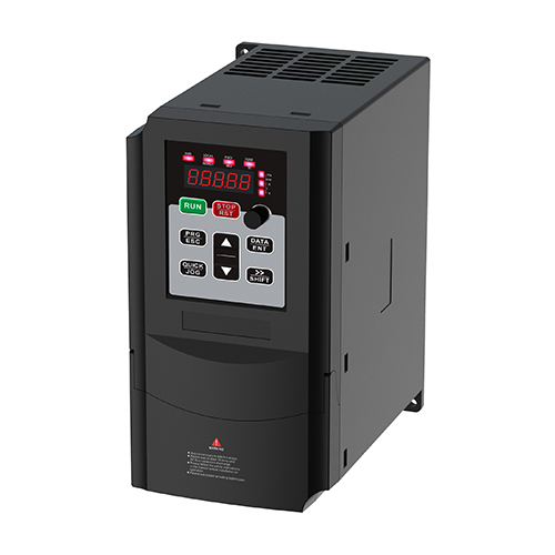
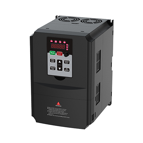
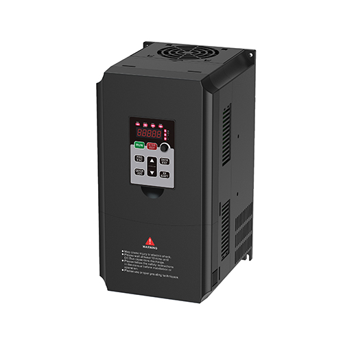
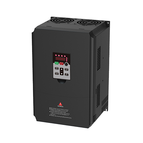
VFD
Variable Frequency Drive
Astro variable frequency drive is suitable for a variety of industrial applications. It is well applicable in all electrical, industrial equipment built with motors, like manufacturing equipment, compressor, elevator, etc. Its reliable SVC vector control and stable operation speed can optimize motor performance and extend its lifecycle, also saving your cost. The Astro variable frequency drive features a faster acceleration/deceleration, faster reacting to load change, and proactive responding while power shedding. In addition, Astro is equipped with a large silent fan, which is conducive to the rapid dissipation of heat; its simplified wiring method and parameter setting are easy to use.

Main Features
- V/F Control , Sensor-less Vector Control (SVC) and Feedback Vector Control (FVC) selectable
- Automatic torque boost and slip compensation
- Fast acceleration and deceleration performance
- 150% torque at 0.5Hz
- Provide precise speed control 0.5%
- Acceptable wide input voltage from 380 (-15%) to 440V (10%)
- Conformal coating to withstand harsh environment
- Built-in RS-485 MODBUS communication
- In-Built dynamic braking unit
- Simplified parameter setting for easy startup
- Standard potentiometer and support external keypad
- Flexible programmable I/O connection
- Control motor to deceleration to stop while sudden power failure to prevent damage
| MODEL | VFD | |
| CAPACITY | 1.5-60 | |
| INPUT | ||
| Frequency Range | ±5% (47.5 ~ 63Hz) | |
| Input Voltage | AC,1PH,220V(-15%)~240V(+10%) AC,3PH,380V(-15%)~440V(+10%) | |
| Rated Frequency | 50/60 Hz | |
| OUTPUT | ||
| AC Voltage Regulation (Batt. Mode) | 0 ~ Input Voltage | |
| Surge Power | 0.1 ~ 500Hz | |
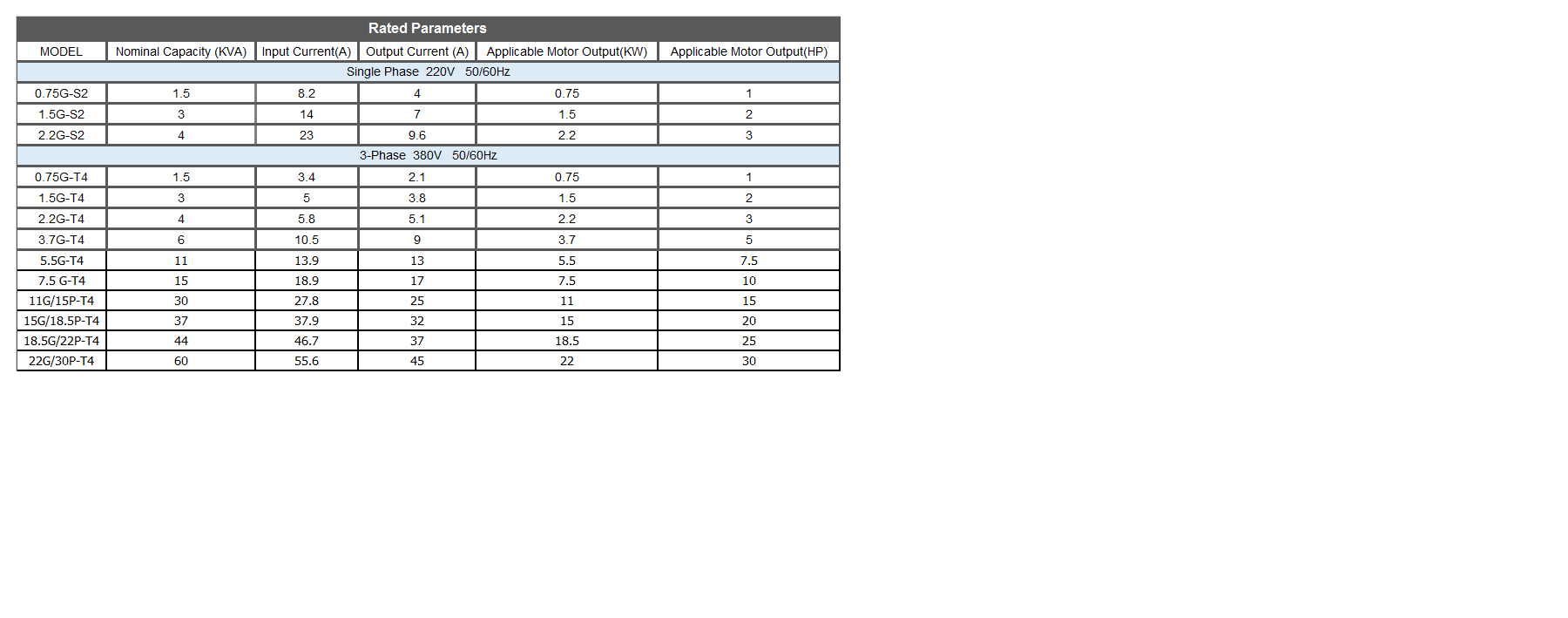
| Efficiency (Peak) | Please refer to Rated Parameter table | |
| Transfer Time | Please refer to Rated Parameter table | |
| ENVIRONMENT | ||
| Noise Level | 50dBA max. | |
| Storage temperature | -20°C ~ 60°C | |
| Operation temperature | -10°C ~ 50°C (If temperarture is higher than 40°C, the output capacity will be derated 1% per 1°C increase) | |
| Storage humidity | <90%RH | |
| Operation humidity | <90%RH | |
| STANDARD | ||
| Safety | Standards:IEC 61800-5-1 | |
| EMC | Standards:IEC 61800-3, C3 | |
| BASIC PARAMETERS | ||
| V/F separation | Full separation, Half separation | |
| Highest frequency | <0.75-3.7K> Vector control: 0~500Hz ;V/F control:0~500Hz <5.5-22K> Vector control: 0~320Hz;V/F control:0~500Hz | |
| Carrier frequency | 0.8kHz~8kHz (Support up to 16KHz carrier frequency) Adjusted automatically according to the load characteristics. | |
| Input frequency resolution | Digital setting: 0.01Hz Analog setting: max. × 0.025% | |
| Control mode | <0.75-3.7K>Open-loop vector control (SVC), V/F control<5.5-22K>Close-loop vector control (FVC), Open-loop vector control (SVC), V/F control | |
| Starting torque | <0.75-3.7K> 0.5Hz/150% (SVC); <5.5-22K> 0.5Hz/150% (SVC), 0Hz / 180% (FVC) | |
| Adjustable speed ratio | <0.75-3.7K> 1:100 (SVC); <5.5-22K> 1:100 (SVC),1:1000 (FVC) | |
| Speed control accuracy | <0.75-3.7K> ±0.5% (SVC); <5.5-22K> ±0.5% (SVC), ±0.02% (FVC) | |
| Overload capability | <0.75-3.7K> 150% of rated current: 60 seconds, 170% of rated current: 12 seconds, 190% of rated current: 1.5 seconds; <5.5-22K> 150% of rated current: 60 seconds,220% of rated current: 1 second | |
| Torque boost | Auto torque boost; Range of manual torque boost 0.1%~30.0% | |
| V/F curve | Three types: Linear, Multi-point, square curve (1.2 power, 1.4 power, 1.6 power, 1.8 power, 2 power) | |
| Acceleration and deceleration time | Linear and S-curve acceleration and deceleration modes available. The range of acceleration and deceleration time is 0.0~6500.0s. | |
| DC braking | Braking frequency: 0.00Hz ~ Maximum frequency Braking time: 0.0s~36.0s Braking current value: 0.0%~100.0% | |
| JOG control | JOG frequency range: 0.00Hz ~ Maximum frequency (5Hz in default). JOG acceleration and deceleration time: 0.0s~6500.0s. | |
| Built-in PID | Simplify the establishment of a closed-loop control system | |
| Automatic voltage regulation (AVR) | Keep the output voltage in stable when the grid voltage fluctuates. | |
| Stall prevention from overvoltage and overcurrent | The current and voltage are limited automatically during operation to prevent frequent tripping due to over-current and over-voltage. | |
| Rapid current limit | Reduce the risk of over-current faults to keep VFD operated normally. | |
| Torque limit and control | Limit the torque automatically during operation to prevent frequent tripping due to over-current. | |
| Braking unit | Built-in braking unit for 22KW and below models | |
| DISPLAY BUTTONS | ||
| LED display | Display parameters | |
| Protective function | Motor short-circuit detection at power-on, output phase loss protection, over-current protection, over-voltage protection, under-voltage protection, overheat protection, overload protection and etc | |
| Key lock and function selections | It allows users to partially or fully lock the keys or define operated range for partial keys to prevent misoperation | |
| Keypad | 0.75K-3.7K model: standard keypad (Optional detachable keypad can be purchased seperately); 5.5K-22K model: standard detachable keypad | |
| Copy parameters (Only for 5.5-22K model) | Parameters can be copied through the standard external keyboard | |
| SPECIAL FEATURES | ||
| Deceleration to stop | In case of instantaneous power drop, the load feedback energy is used to compensate the voltage drop to maintain the inverter’s normal operation over that short period. | |
| Rapid current limit | Reduce the risk of over-current faults to keep VFD operated normally. | |
| Timer control | Setting range: 0.0Min ~ 6500.0Min | |
| Communication | <0.75-3.7K> Modbus; <5.5-22K> Modbus、CANLink、CANOpen、Profibus-DP、ProfiNET | |
| INPUT/OUTPUT | ||
| Command source | Operation panel, control terminal and serial communication port. | |
| Frequency source | <0.75-3.7K> Digital setting, Analog voltage setting, Analog current setting, Pulse setting and Serial port setting.<5.5-22K>Keyboard setting (saving/not saving when power-off), analog voltage setting, analog current setting, pulse setting, serial port setting, panel encoder setting, multi-speed running setting, simple PLC setting, PID setting, analog A13 setting (key knob).It can be switched in multiple ways. | |
| Auxiliary frequency source | <0.75-3.7K> 5 options to provide flexible auxiliary frequency fine-tuning and frequency synthesis. <5.5-22K>10 options to provide flexible auxiliary frequency fine-tuning and frequency synthesis. | |
| Input terminals | <0.75-3.7K> 4 digital input terminals, one of which supports high-frequency pulse input up to 50kHz, 1 analog input terminal supporting 0 ~ 10V voltage input or 0 ~ 20mA current input, 1 rotary potentiometer analog input; <5.5-22K>7 digital input terminals, one of which supports high-speed pulse input up to 100kHz, 2 analog input terminals, support 0~10V voltage input or 0~20mA current input, 1 rotary potentiometer analog input | |
| Output terminals | <0.75-3.7K>1 high-speed pulse output terminal supporting 50kHz step-wave signal output, 1 relay output terminal, 1 analog output terminal supporting 0~20mA current output or 0~10V voltage output<5.5-22K>1 high-speed pulse output terminal, support 100kHz square wave signal output, 1 digital output terminal, 2 relay output terminals, 2 analog output terminals, support 0~20mA current output or 0~10V voltage output | |
| INTERACE | ||
| Communication Port | RS-485 | |
General
CAPACITY
| VFD | 1.5-60 |
|---|
INPUT
Frequency Range
| VFD | ±5% (47.5 ~ 63Hz) |
|---|
Input Voltage
| VFD | AC,1PH,220V(-15%)~240V(+10%) AC,3PH,380V(-15%)~440V(+10%) |
|---|
Rated Frequency
| VFD | 50/60 Hz |
|---|
OUTPUT
AC Voltage Regulation (Batt. Mode)
| VFD | 0 ~ Input Voltage |
|---|
Surge Power
| VFD | 0.1 ~ 500Hz |
|---|
Efficiency (Peak)
| VFD | Please refer to Rated Parameter table |
|---|
Transfer Time
| VFD | Please refer to Rated Parameter table |
|---|
ENVIRONMENT
Noise Level
| VFD | 50dBA max. |
|---|
Storage temperature
| VFD | -20°C ~ 60°C |
|---|
Operation temperature
| VFD | -10°C ~ 50°C (If temperarture is higher than 40°C, the output capacity will be derated 1% per 1°C increase) |
|---|
Storage humidity
| VFD | <90%RH |
|---|
Operation humidity
| VFD | <90%RH |
|---|
STANDARD
Safety
| VFD | Standards:IEC 61800-5-1 |
|---|
EMC
| VFD | Standards:IEC 61800-3, C3 |
|---|
BASIC PARAMETERS
V/F separation
| VFD | Full separation, Half separation |
|---|
Highest frequency
| VFD | <0.75-3.7K> Vector control: 0~500Hz ;V/F control:0~500Hz <5.5-22K> Vector control: 0~320Hz;V/F control:0~500Hz |
|---|
Carrier frequency
| VFD | 0.8kHz~8kHz (Support up to 16KHz carrier frequency) Adjusted automatically according to the load characteristics. |
|---|
Input frequency resolution
| VFD | Digital setting: 0.01Hz Analog setting: max. × 0.025% |
|---|
Control mode
| VFD | <0.75-3.7K>Open-loop vector control (SVC), V/F control<5.5-22K>Close-loop vector control (FVC), Open-loop vector control (SVC), V/F control |
|---|
Starting torque
| VFD | <0.75-3.7K> 0.5Hz/150% (SVC); <5.5-22K> 0.5Hz/150% (SVC), 0Hz / 180% (FVC) |
|---|
Adjustable speed ratio
| VFD | <0.75-3.7K> 1:100 (SVC); <5.5-22K> 1:100 (SVC),1:1000 (FVC) |
|---|
Speed control accuracy
| VFD | <0.75-3.7K> ±0.5% (SVC); <5.5-22K> ±0.5% (SVC), ±0.02% (FVC) |
|---|
Overload capability
| VFD | <0.75-3.7K> 150% of rated current: 60 seconds, 170% of rated current: 12 seconds, 190% of rated current: 1.5 seconds; <5.5-22K> 150% of rated current: 60 seconds,220% of rated current: 1 second |
|---|
Torque boost
| VFD | Auto torque boost; Range of manual torque boost 0.1%~30.0% |
|---|
V/F curve
| VFD | Three types: Linear, Multi-point, square curve (1.2 power, 1.4 power, 1.6 power, 1.8 power, 2 power) |
|---|
Acceleration and deceleration time
| VFD | Linear and S-curve acceleration and deceleration modes available. The range of acceleration and deceleration time is 0.0~6500.0s. |
|---|
DC braking
| VFD | Braking frequency: 0.00Hz ~ Maximum frequency Braking time: 0.0s~36.0s Braking current value: 0.0%~100.0% |
|---|
JOG control
| VFD | JOG frequency range: 0.00Hz ~ Maximum frequency (5Hz in default). JOG acceleration and deceleration time: 0.0s~6500.0s. |
|---|
Built-in PID
| VFD | Simplify the establishment of a closed-loop control system |
|---|
Automatic voltage regulation (AVR)
| VFD | Keep the output voltage in stable when the grid voltage fluctuates. |
|---|
Stall prevention from overvoltage and overcurrent
| VFD | The current and voltage are limited automatically during operation to prevent frequent tripping due to over-current and over-voltage. |
|---|
Rapid current limit
| VFD | Reduce the risk of over-current faults to keep VFD operated normally. |
|---|
Torque limit and control
| VFD | Limit the torque automatically during operation to prevent frequent tripping due to over-current. |
|---|
Braking unit
| VFD | Built-in braking unit for 22KW and below models |
|---|
DISPLAY BUTTONS
LED display
| VFD | Display parameters |
|---|
Protective function
| VFD | Motor short-circuit detection at power-on, output phase loss protection, over-current protection, over-voltage protection, under-voltage protection, overheat protection, overload protection and etc |
|---|
Key lock and function selections
| VFD | It allows users to partially or fully lock the keys or define operated range for partial keys to prevent misoperation |
|---|
Keypad
| VFD | 0.75K-3.7K model: standard keypad (Optional detachable keypad can be purchased seperately); 5.5K-22K model: standard detachable keypad |
|---|
Copy parameters
(Only for 5.5-22K model)
| VFD | Parameters can be copied through the standard external keyboard |
|---|
SPECIAL FEATURES
Deceleration to stop
| VFD | In case of instantaneous power drop, the load feedback energy is used to compensate the voltage drop to maintain the inverter’s normal operation over that short period. |
|---|
Rapid current limit
| VFD | Reduce the risk of over-current faults to keep VFD operated normally. |
|---|
Timer control
| VFD | Setting range: 0.0Min ~ 6500.0Min |
|---|
Communication
| VFD | <0.75-3.7K> Modbus; <5.5-22K> Modbus、CANLink、CANOpen、Profibus-DP、ProfiNET |
|---|
INPUT/OUTPUT
Command source
| VFD | Operation panel, control terminal and serial communication port. |
|---|
Frequency source
| VFD | <0.75-3.7K> Digital setting, Analog voltage setting, Analog current setting, Pulse setting and Serial port setting.<5.5-22K>Keyboard setting (saving/not saving when power-off), analog voltage setting, analog current setting, pulse setting, serial port setting, panel encoder setting, multi-speed running setting, simple PLC setting, PID setting, analog A13 setting (key knob).It can be switched in multiple ways. |
|---|
Auxiliary frequency source
| VFD | <0.75-3.7K> 5 options to provide flexible auxiliary frequency fine-tuning and frequency synthesis. <5.5-22K>10 options to provide flexible auxiliary frequency fine-tuning and frequency synthesis. |
|---|
Input terminals
| VFD | <0.75-3.7K> 4 digital input terminals, one of which supports high-frequency pulse input up to 50kHz, 1 analog input terminal supporting 0 ~ 10V voltage input or 0 ~ 20mA current input, 1 rotary potentiometer analog input; <5.5-22K>7 digital input terminals, one of which supports high-speed pulse input up to 100kHz, 2 analog input terminals, support 0~10V voltage input or 0~20mA current input, 1 rotary potentiometer analog input |
|---|
Output terminals
| VFD | <0.75-3.7K>1 high-speed pulse output terminal supporting 50kHz step-wave signal output, 1 relay output terminal, 1 analog output terminal supporting 0~20mA current output or 0~10V voltage output<5.5-22K>1 high-speed pulse output terminal, support 100kHz square wave signal output, 1 digital output terminal, 2 relay output terminals, 2 analog output terminals, support 0~20mA current output or 0~10V voltage output |
|---|
INTERACE
Communication Port
| VFD | RS-485 |
|---|
| Brochure | VFD_Brochure | |
| Manual | VFD 0.75-3.7K_Manual | |
| Manual | VFD 5.5-22K_Manual |
VFD VFD Variable Frequency Drive
Related Products

iMaster
Solar Pump Inverter

Pioneer
Variable Frequency Drive
We have received your membership application and will reply as soon as within 24 hours, before that, please browse our website, thank you.